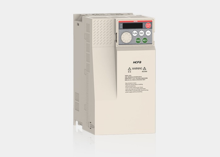
As a trusted HCFA distributor, we provide industry-proven VFDs that deliver robust speed control for AC motors. These drives are built to enhance system efficiency, ensure operational stability, and incorporate critical protection features for a wide array of industrial applications. Explore our range to find the precise drive solution to meet your technical and performance requirements."
| Technical Specification | |||||||||||||||||||||
|---|---|---|---|---|---|---|---|---|---|---|---|---|---|---|---|---|---|---|---|---|---|
| Power[kW] | 0.75* | 1.5* | 2.2* | 3.7* | 5.5* | 7.5* | 11 | 15 | 18.5 | 22 | 30 | 37 | 45 | 55 | 75 | 90 | 110 | 132 | 160 | ||
| Max. motor capacity[kW] | 0.75 | 1.5 | 2.2 | 3.7 | 5.5 | 7.5 | 11 | 15 | 18.5 | 22 | 30 | 37 | 45 | 55 | 75 | 90 | 110 | 132 | 160 | ||
| Rated output current[Arms] | 2.1 | 3.8 | 5.1 | 9 | 13 | 17 | 25 | 32 | 37 | 45 | 60 | 75 | 91 | 112 | 150 | 176 | 210 | 253 | 304 | ||
| Input current[Arms] | 3.4 | 5 | 5.8 | 10.5 | 14.6 | 20.5 | 26 | 35 | 38.5 | 46.5 | 62 | 76 | 92 | 113 | 157 | 180 | 214 | 256 | 307 | ||
| Power capacity[kVA] | 1.5 | 3 | 4 | 5.9 | 8.9 | 11 | 17 | 21 | 24 | 30 | 40 | 57 | 69 | 85 | 114 | 134 | 160 | 192 | 231 | ||
| Braking resistor | External brake resistor | Resistance value Ω | 800 | 380 | 260 | 150 | 100 | 75 | 50 | 38 | 32 | 27 | 20 | 16 | 13 | 10.5 | 7.7 | 6 | 5 | 4 | 3 |
| Capacity[kW] | 0.15 | 0.3 | 0.44 | 0.75 | 1.1 | 1.5 | 2.2 | 3 | 4 | 4.5 | 6 | 7 | 9 | 11 | 15 | 18 | 22 | 24 | 26 | ||
| Mini braking Resistance(Ω) | 96 | 96 | 96 | 32 | 32 | 32 | 24 | 24 | 24 | 24 | 20 | 16 | 16 | 8 | 8 | 5 | 4 | 3 | 2 | ||
| Rated output voltage[V] | 0~Input voltage | ||||||||||||||||||||
| Max. output frequency | 0.00-599.00Hz | ||||||||||||||||||||
| Carrier frequency | VF: 1KHz~16KHz SVC: 1KHz~10KHz FVC: 1KHz~10KHz | ||||||||||||||||||||
| Overload capacity | 110% rated current for 1 hour, 150% rated current for 1 minute, 180% rated current for 3 seconds | ||||||||||||||||||||
| Input power voltage[V] | Three-phase 380~480V AC, 50/60Hz-15% ~10% actual allowable voltage range Three-phase 323V ~528V AC | ||||||||||||||||||||
| Performance Specification | ||||
|---|---|---|---|---|
| Max. Frequency | 0.00 - 599.00Hz (Except non-standard models) | |||
| Carrier frequency | VF: 1.500KHz~16.000KHz; SVC: 1.500KHz~10.000KHz; The carrier frequency can be automatically adjusted according to the IGBT temperature and load characteristics |
|||
| Input frequency resolution | Digital setting: 0.01Hz Analog setting: Max. frequency × 0.025% |
|||
| Motor type and control method | 3-phase asynchronous motor: VF control, SVC, FVC PM-SM*: SVC, FVC |
|||
| Starting torque | 150% (SVC 0.5Hz) | |||
| Speed range | 1 : 50 VF control; 1 : 100 SVC; 1 : 1000 FVC | |||
| Speed control accuracy | ±1.0% VF control; ±0.5% SVC; ±0.02% FVC | |||
| Speed control accuracy | ±1.0% VF control; ±0.5% SVC; ±0.02% FVC | |||
| Overload capacity | 110% rated current for 1h, 150% rated current for 1 min, 180% rated current for 3s | |||
| Torque boost | Automatic torque boost; manual torque boost 0.1%~30.0% | |||
| Torque boost | Automatic torque boost; manual torque boost 0.1%~30.0% | |||
| Torque boost | Automatic torque boost; manual torque boost 0.1%~30.0% | |||
| VF curve | Linear VF, multi-point VF, square VF, VF separation | |||
| Automatic voltage regulation (AVR) | When the grid voltage changes, it can automatically keep the output voltage constant | |||
| DC braking | DC braking frequency: 0.00Hz~max. frequency; braking time: 0.0s~30.0s; braking action voltage value: 0.00%~50.00% | |||
| Jog control | Jog frequency range: 0.00Hz~max. frequency; Jog acceleration and deceleration time 0.00s~600.00s | |||
| Simple PLC, multi-speed operation | Up to 16 speeds can be achieved through built-in PLC or control terminals | |||
| Built-in PID | 2 sets of PID parameters can easily realize closed-loop process control system | |||
| DC braking | DC braking frequency: 0.00Hz~max. frequency; braking time: 0.0s~30.0s; braking action voltage value: 0.00%~50.00% | |||
| DC braking | DC braking frequency: 0.00Hz~max. frequency; braking time: 0.0s~30.0s; braking action voltage value: 0.00%~50.00% | |||
| Custom button | Support optional programmable buttons, Jog, Positive/negative input switching function, Function code display switching, Start/Stop command switching, Free stop and Emergency stop |
| Communication bus | Modbus, CANOpen, EtherCAT, EtherNet IP, Modbus-TCP, Profinet |
| STO function* | STO function (optional) |
| Custom fault function | Users can customize analog or digital faults |
| Acceleration/deceleration curves | Linear acceleration/deceleration method, S-curve acceleration/deceleration method, lifting load acceleration/deceleration curve method |
| Electricity metering | Can calculate the power consumption per unit time |
| Display mode switching | The display mode can be quick menu mode or a mode different from the factory default, which is convenient for debugging |
| Run command channel | 3 methods: operation panel setting, control terminal setting, communication setting. Can be switched |
| Frequency source | 8 frequency sources: Digital setting, analog voltage setting, analog current setting, pulse setting, multi-speed, PLC, PID, communication setting |
| Wireless communications | Wifi, Bluetooth, and IoT communication functions are optional |
| Speed tracking | Improve speed tracking function (IM/PM), start in non-stationary state |
| Weak magnetic properties | Improve speed tracking function (IM/PM), start in non-stationary state |
| Active preheating | Active motor preheating function reduces the viscosity of grease at low temperatures and enhances low-temperature starting capability |
| Overload and load reduction | Introduce overload and load reduction function to avoid downtime due to faults |
| Wide voltage characteristics | Wide voltage range 380V~480V (-15%~10%) |
| LED display | With LED keyboard to realize parameter setting and status monitoring functions |
| Protection function | WOvercurrent protection, overvoltage protection, undervoltage protection, overheating protection, overload protection, etc. |
| Communication expansion card | Modbus, CANOpen, EtherCAT, EtherNet IP, Modbus-TCP, Profinet |
| PG expansion card | Supports differential type, absolute value, resolver, Sin and Cos |
| I/O expansion card | DI, DO, AI, AO |
| PLC expansion card | Support PLC program development* |
| Application location | Indoors, free from direct sunlight, dust, corrosive gas, flammable gas, oil mist, water vapor, dripping water or salt, etc. |
| Altitude | Below 1000m (please derate for altitudes above 1000m) |
| Ambient temperature | -10°C~+60°C (When the ambient temperature is between 50°C~60°C, the rating should be derated by 10% for every +5°C of temperature) |
| Humidity | Less than 95%RH, no condensation |
| Vibration | During operation: 3.5mm, peak-to-peak from 5~9Hz; 1.5g, from 9~15Hz; Comply with IEC/EN60068-2-6 |
| Storage temperature | -30°C~+80°C |
| Protection level | IP20 |
| Cooling method | Forced air cooling |
| Shock | During operation: 15g, 11ms; Comply with IEC/EN60068-2-27 |
| I/O expansion card | DI, DO, AI, AO |
| PLC expansion card | Support PLC program development* |
| Power[kW] | 0.4 | 0.75 | 1.5 | 2.2* | ||
| Maximum adaptable motor capacity[kW] | 0.4 | 0.75 | 1.5 | 2.2 | ||
| Rated output current[Arms] | 3.5 | 4.8 | 7.5 | 9 | ||
| Instantaneous max. output current[Arms] | 5.2 | 8.5 | 13.0 | 16.2 | ||
| Input current[Arms] | 3.8 | 5.3 | 8.6 | 11.5 | ||
| Power capacity[kVA] | 1.1 | 2.1 | 4.2 | 5.3 | ||
| Heat and power loss[W] | 35 | 52 | 88 | 110 | ||
| Braking resistor | External braking resistor | Resistance value Ω | 300 | 170 | 80 | 55 |
| Capacity[W] | 90 | 160 | 340 | 500 | ||
| Minimum braking resistor(Ω) | 48 | 48 | 32 | 16 | ||
| Rated output voltage[V] | 0~input voltage | |||||
| Max output Frequency | 0.00-599.00Hz | |||||
| Carrier frequency | VF:1.500KHz SVC:1.500KHz~10.000KHz | |||||
| Overload capacity | 110% of rated current for 1 hour, 150% of rated current for 1 min, 180% of rated current for 3 sec | |||||
| Input supply voltage[V] | Three phase AC200 ~ 240V, 50/60Hz -15% ~ -10% actual voltage range Three-phase AC170V~ 264v | |||||
| Power[kW] | 0.4 | 0.75 | 1.5 | 2.2 | 3.7 | 5.5 | 7.5 | 11* | 15* | 18.5* | 22* | ||
| Maximum adaptable motor capacity[kW] | 0.4 | 0.75 | 1.5 | 2.2 | 3.7 | 5.5 | 7.5 | 11 | 15 | 18.5 | 22 | ||
| Rated output current[Arms] | 2.0 | 3.5 | 4.8 | 7.2 | 9 | 13 | 17 | 25 | 32 | 37 | 45 | ||
| Instantaneous max. output current[Arms] | 3.6 | 5.2 | 8.5 | 13.0 | 16.2 | 23.4 | 30.6 | 45.0 | 57.6 | 66.6 | 81.0 | ||
| Input current[Arms] | 2.3 | 3.8 | 5.3 | 8.6 | 11.5 | 16.6 | 21.9 | 32.2 | 41.2 | 50 | 57 | ||
| Power capacity[kVA] | 2 | 2.8 | 5 | 6.7 | 12 | 17.5 | 22.6 | 33.5 | 42.8 | 45 | 52 | ||
| Heat and power loss[W] | 39 | 46 | 68 | 80 | 140 | 200 | 240 | 355 | 455 | 476 | 550 | ||
| Braking resistor | External braking resistor | Resistance value Ω | 1450 | 800 | 380 | 260 | 150 | 100 | 75 | 50 | 38 | 32 | 27 |
| Capacity[W] | 80 | 140 | 300 | 440 | 750 | 1100 | 1500 | 2200 | 3000 | 4000 | 4500 | ||
| Minimum braking resistor(Ω) | 96 | 96 | 96 | 96 | 32 | 32 | 32 | 20 | 20 | 24 | 24 | ||
| Rated output voltage[V] | 0~input voltage | ||||||||||||
| Max output Frequency | 0.00-599.00Hz | ||||||||||||
| Carrier frequency | VF:1.500KHz SVC:1.500KHz~10.000KHz | ||||||||||||
| Overload capacity | 110% of rated current for 1 hour, 150% of rated current for 1 min, 180% of rated current for 3 sec | ||||||||||||
| Input supply voltage[V] | Three phase AC380 ~ 480V, 50/60Hz -15% ~ -10% actual voltage range Three-phase AC323V~ 528V | ||||||||||||
| Performance Specification | ||||
|---|---|---|---|---|
| Max. Frequency | 0.00 - 599.00Hz (Except non-standard models) | |||
| Carrier frequency | VF: 1.500KHz~16.000KHz; SVC: 1.500KHz~10.000KHz; The carrier frequency can be automatically adjusted according to the IGBT temperature and load characteristics |
|||
| Input frequency resolution | Digital setting: 0.01Hz Analog setting: Max. frequency × 0.025% |
|||
| Motor type and control method | 3-phase asynchronous motor: VF control, SVC, FVC PM-SM*: SVC, FVC |
|||
| Starting torque | 150% (SVC 0.5Hz) | |||
| Speed range | 1 : 50 VF control; 1 : 100 SVC; 1 : 1000 FVC | |||
| Speed control accuracy | ±1.0% VF control; ±0.5% SVC; ±0.02% FVC | |||
| Speed control accuracy | ±1.0% VF control; ±0.5% SVC; ±0.02% FVC | |||
| Overload capacity | 110% rated current for 1h, 150% rated current for 1 min, 180% rated current for 3s | |||
| Torque boost | Automatic torque boost; manual torque boost 0.1%~30.0% | |||
| Torque boost | Automatic torque boost; manual torque boost 0.1%~30.0% | |||
| Torque boost | Automatic torque boost; manual torque boost 0.1%~30.0% | |||
| VF curve | Linear VF, multi-point VF, square VF, VF separation | |||
| Automatic voltage regulation (AVR) | When the grid voltage changes, it can automatically keep the output voltage constant | |||
| DC braking | DC braking frequency: 0.00Hz~max. frequency; braking time: 0.0s~30.0s; braking action voltage value: 0.00%~50.00% | |||
| Jog control | Jog frequency range: 0.00Hz~max. frequency; Jog acceleration and deceleration time 0.00s~600.00s | |||
| Simple PLC, multi-speed operation | Up to 16 speeds can be achieved through built-in PLC or control terminals | |||
| Built-in PID | 2 sets of PID parameters can easily realize closed-loop process control system | |||
| DC braking | DC braking frequency: 0.00Hz~max. frequency; braking time: 0.0s~30.0s; braking action voltage value: 0.00%~50.00% | |||
| DC braking | DC braking frequency: 0.00Hz~max. frequency; braking time: 0.0s~30.0s; braking action voltage value: 0.00%~50.00% | |||
| Custom button | Support optional programmable buttons, Jog, Positive/negative input switching function, Function code display switching, Start/Stop command switching, Free stop and Emergency stop |
| Communication bus | Modbus, CANOpen, EtherCAT, EtherNet IP, Modbus-TCP, Profinet |
| STO function* | STO function (optional) |
| Custom fault function | Users can customize analog or digital faults |
| Acceleration/deceleration curves | Linear acceleration/deceleration method, S-curve acceleration/deceleration method, lifting load acceleration/deceleration curve method |
| Electricity metering | Can calculate the power consumption per unit time |
| Display mode switching | The display mode can be quick menu mode or a mode different from the factory default, which is convenient for debugging |
| Run command channel | 3 methods: operation panel setting, control terminal setting, communication setting. Can be switched |
| Frequency source | 8 frequency sources: Digital setting, analog voltage setting, analog current setting, pulse setting, multi-speed, PLC, PID, communication setting |
| Wireless communications | Wifi, Bluetooth, and IoT communication functions are optional |
| Speed tracking | Improve speed tracking function (IM/PM), start in non-stationary state |
| Weak magnetic properties | Improve speed tracking function (IM/PM), start in non-stationary state |
| Active preheating | Active motor preheating function reduces the viscosity of grease at low temperatures and enhances low-temperature starting capability |
| Overload and load reduction | Introduce overload and load reduction function to avoid downtime due to faults |
| Wide voltage characteristics | Wide voltage range 380V~480V (-15%~10%) |
| LED display | With LED keyboard to realize parameter setting and status monitoring functions |
| Protection function | WOvercurrent protection, overvoltage protection, undervoltage protection, overheating protection, overload protection, etc. |
| Communication expansion card | Modbus, CANOpen, EtherCAT, EtherNet IP, Modbus-TCP, Profinet |
| PG expansion card | Supports differential type, absolute value, resolver, Sin and Cos |
| I/O expansion card | DI, DO, AI, AO |
| PLC expansion card | Support PLC program development* |
| Technical Specification | |||
|---|---|---|---|
| Power input | Rated voltage | Single-phase 220V: Constant voltage fluctuation ±10%, transient fluctuation -15%~+10% Three-phase 220V: Constant voltage fluctuation ±10%, transient fluctuation -15%~+10% Three-phase 380V: Constant voltage fluctuation ±10%, transient fluctuation -15%~+10% That is 323-437V; Voltage imbalance <3%, the distortion rate in accordance with IEC61800-2. |
|
| Rated input current | Refer to 2-1 | ||
| Rated frequency | 50Hz/60Hz, fluctuation range ±5% | ||
| Power output | Applicable motor | Refer to 2-1 | |
| Rated capacity | Refer to 2-1 | ||
| Rated current | Refer to 2-1 | ||
| Output voltage | Three-phase, 0V to the rated voltage, error less than ±3% | ||
| Basic functions | Max frequency | 0Hz~500Hz, 0Hz~3000Hz, can be customized according to customer needs | |
| Carrier frequency | 1.0kHz~16.0kHz, can be adjusted automatically | ||
| Input frequency resolution | 0.01Hz (Digital setting) | ||
| Control mode | Speed control (SVC), torque control (SVC), speed control (FVC), torque control (FVC), V/F control | ||
| Startup torque | 0.25Hz/150% (SVC) | 0Hz/180% (FVC) | |
| Speed range | 1:100 (SVC) | 1:1000 (FVC) | |
| Speed stability accuracy | ±0.5% (SVC) ±0.02% (FVC) |
±0.02% (FVC) | |
| Torque control accuracy | ±5% (FVC) ★ | ||
| Overload capacity | G models: 60s for 150% rated current, 1s for 200% rated current | ||
| Torque boost | Automatic boost; Customized boost 0.1% to 30.0% | ||
| Acceleration/deceleration curve | Straight-line or S-curve. Four kinds of acceleration/deceleration time, range: 0.0s~6500.0s | ||
| DC injection braking | DC injection braking frequency: 0Hz to max frequency, DC injection braking time: 0.0s to 60.0s. Current level of DC injection braking: 0% to 100% | ||
| Jog running | Frequency range of jog running: 0.00Hz~P20.00, Acceleration/Deceleration time of jog running: 0.0s to 6500.0s | ||
| Onboard multiple preset speeds | The VFD can realize up to 16 speeds by using simple PLC function or by using digital input signals | ||
| Onboard PID | The VFD can realize proportional-integral-derivative (PID) function in the closed-loop control | ||
| Automatic voltage regulation (AVR) | The system maintains a constant output voltage automatically when the grid voltage fluctuates | ||
| Overcurrent stall control | The VFD can limit the output current automatically when the load changes in V/F operation | ||
| Overcurrent fast prevention | The function helps to avoid frequent overcurrent faults to guarantee the VFD operates normally | ||
| Overvoltage stall control | The system limits the energy feedback automatically during operation to prevent frequent or excessive trips when frequency changes | ||
| Oscillation suppression | Optimize the V/F oscillation suppression to keep the stable operation | ||
| Technical Specification | ||
|---|---|---|
| Individualized Functions | Power dip ride-through | Load feedback energy compensates for any voltage reduction, allowing the VFD to continue to operate for a short time during power dips |
| Timing control | Timing control: Time setting range 0.0min~6500.0min | |
| Dual-motor switcher | The VFD have two groups of motor parameters and can control up to two motors | |
| Multiple fieldbus supported | Multiple fieldbus: Modbus-RTU, CANopen | |
| PT100 overheat protection | Optional I/O extension card★, analog input, AI3 can accept motor temperature sensor input (PT100/PT1000) | |
| Multiple encoders types supported | Support incremental encoders | |
| RUN | Command source | Different methods of switching, such as Operating panel, Terminal I/O control, Serial communication |
| Main frequency reference setting channels | Supports up to 10 frequency reference setting channels and allows different methods of switching: Digital setting, Analog voltage reference, Analog current reference, Pulse reference, Communication reference | |
| Auxiliary frequency reference setting channel | Supports 9 auxiliary frequency sources, and allows linking of the auxiliary frequency and main& auxiliary calculation | |
| Input terminals | Standard: 7 digital input (DI) terminals, one of which supports up to 100kHz high-speed pulse input. 3 analog input (AI) terminals: AI1: Support 0 to10V voltage input AI2: Support 0 to 10V voltage input or 0 to 20mA current input AI3: Support -10 to 10V voltage input Extension capacity★: Can be customized according to customer needs |
|
| Output terminals | Standard: 2 analog output terminal, support 0 to 10V voltage output or 0(or 4) to 20mA current output 2 digital output terminal, one of which supports high-speed pulse output terminal for a square-wave signal output in the frequency 0 to 100kHz 1 relay output terminal Extension capacity★: Can be customized according to customer needs |
|
| Display & operating panel | LED display | Display and operating panel |
| LCD display | Can be selected according to user needs | |
| Parameter copy | The parameters can be quickly copied through the LCD operation panel | |
| Key locking and function selection | Keys on the LCD control panel can be locked or partially locked electronically to prevent accidental operation. The range of some functions can be limited to a permitted range to prevent incorrect settings | |
| Protection function | Short-circuit protection, Input/output phase loss protection, Overcurrent protection, Overvoltage protection, Undervoltage protection, Overheat protection, Overload protection | |
| Optional accessories | LCD operation panel, brake components, I/O extension card★, CANopen communication card, incremental encoder PG card | |
| Environment | Installation location | Install the VFD indoors and protected from direct sunlight, dust, corrosive or combustible gases, oil smoke, vapour, ingress from water or any other liquid, and salt |
| Altitude | Below 1000 m (If the altitude exceeds 1000 m, de-rate the VFD.) | |
| Operation temperature | -10°C~+40°C (If the ambient temperature is 40°C to 50°C, de-rate the VFD.) | |
| Humidity | Less than 95%RH, non-condensing | |
| Vibration | Less than 5.9m/s2 (0.6g) | |
| Storage temperature | -20°C~+60°C | |
| Protection level | IP20 | |
| Cooling method | Forced air cooling | |
| Product Specification | |||||||
|---|---|---|---|---|---|---|---|
(kVA) |
|||||||
| E220V | Single phase power 220V(-15%~+10%), 50/60Hz |
E220-0.75G3BE-00 | 1.5 | 8.2 | 4 | 0.75 | 1 |
| E220-1.5G3BE-00 | 3 | 14 | 7 | 1.5 | 2 | ||
| E220-2.2G3BE-00 | 4 | 23 | 9.6 | 2.2 | 3 | ||
| Three phase power 220V(-15%~+10%), 50/60Hz |
E220-0.75G3BE-00 | 3 | 5 | 4 | 0.75 | 1 | |
| E220-1.5G3BE-00 | 4 | 8 | 7 | 1.5 | 2 | ||
| E220-2.2G3BE-00 | 6 | 10.5 | 9.6 | 2.2 | 3 | ||
| E220-3.7G3BE-00 | 8.9 | 14.6 | 13 | 3.7 | 5 | ||
| E220V | Three phase power 380V(-15%~+10%), 50/60Hz |
E380-0.75G3BE-00 | 1.5 | 3.4 | 2.1 | 0.75 | 1 |
| E380-1.5G3BE-00 | 3 | 5 | 3.7 | 1.5 | 2 | ||
| E380-2.2G3BE-00 | 4 | 5.8 | 5 | 2.2 | 3 | ||
| E380-3.7G3BE-00 | 5.9 | 10.5 | 9 | 3.7 | 5 | ||
| E380-5.5G3BE-00 | 8.9 | 14.6 | 13 | 5.5 | 7.5 | ||
| E380-7.5G3BE-00 | 11 | 20.5 | 17 | 7.5 | 10 | ||
| E380-11G3BE-00 | 17 | 26 | 25 | 11 | 15 | ||
| E380-15G3BE-00 | 21 | 35 | 32 | 15 | 20 | ||
| E380-18.5G3BE-00 | 24 | 38.5 | 37 | 18.5 | 25 | ||
| E380-22G3BE-00 | 30 | 46.5 | 45 | 22 | 30 | ||
| E380-30G3NE-00 | 40 | 62 | 60 | 30 | 40 | ||
| E380-37G3NE-00 | 50 | 76 | 75 | 37 | 50 | ||
| E380-30G3BE-00 | 40 | 62 | 60 | 30 | 40 | ||
| E380-37G3BE-00 | 50 | 76 | 75 | 37 | 50 | ||